 Final version")
 Final version")
 Final version")
 Final version")
 Final version")
 Final version")
 Final version")
 Final version")
 Final version")
Interference pattern
var i(ant) is a generative system exploring interference patterns and emergent structures. Each mint reveals unique echoes of a shifting topology.
Interference pattern
var i(ant) is a generative system exploring interference patterns and emergent structures. Each mint reveals unique echoes of a shifting topology.
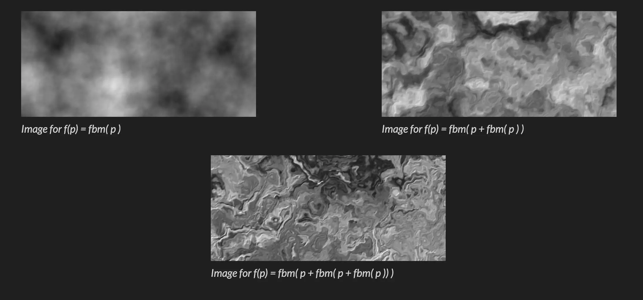
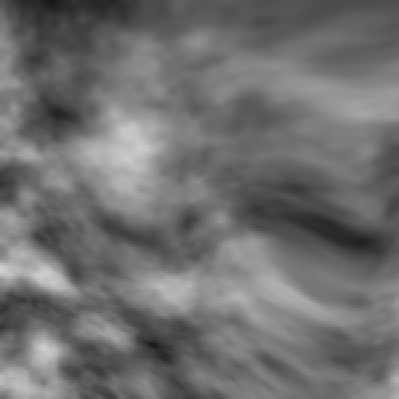
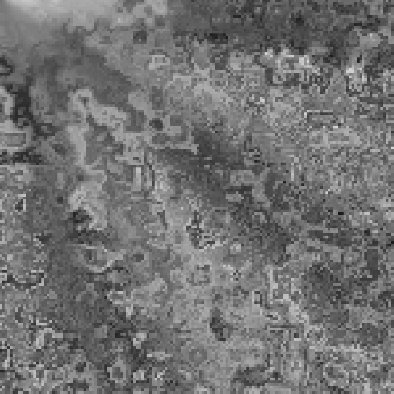
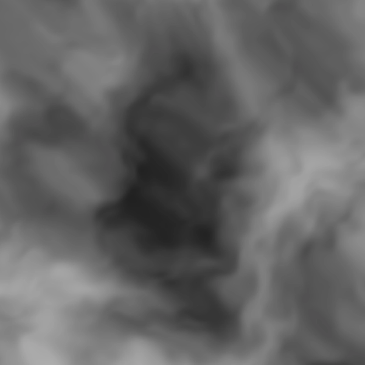
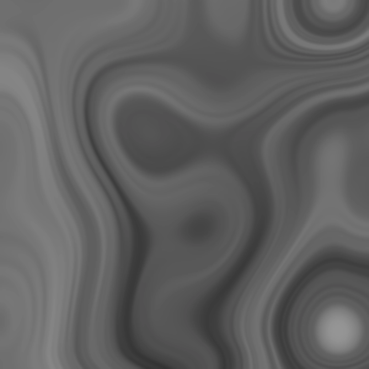
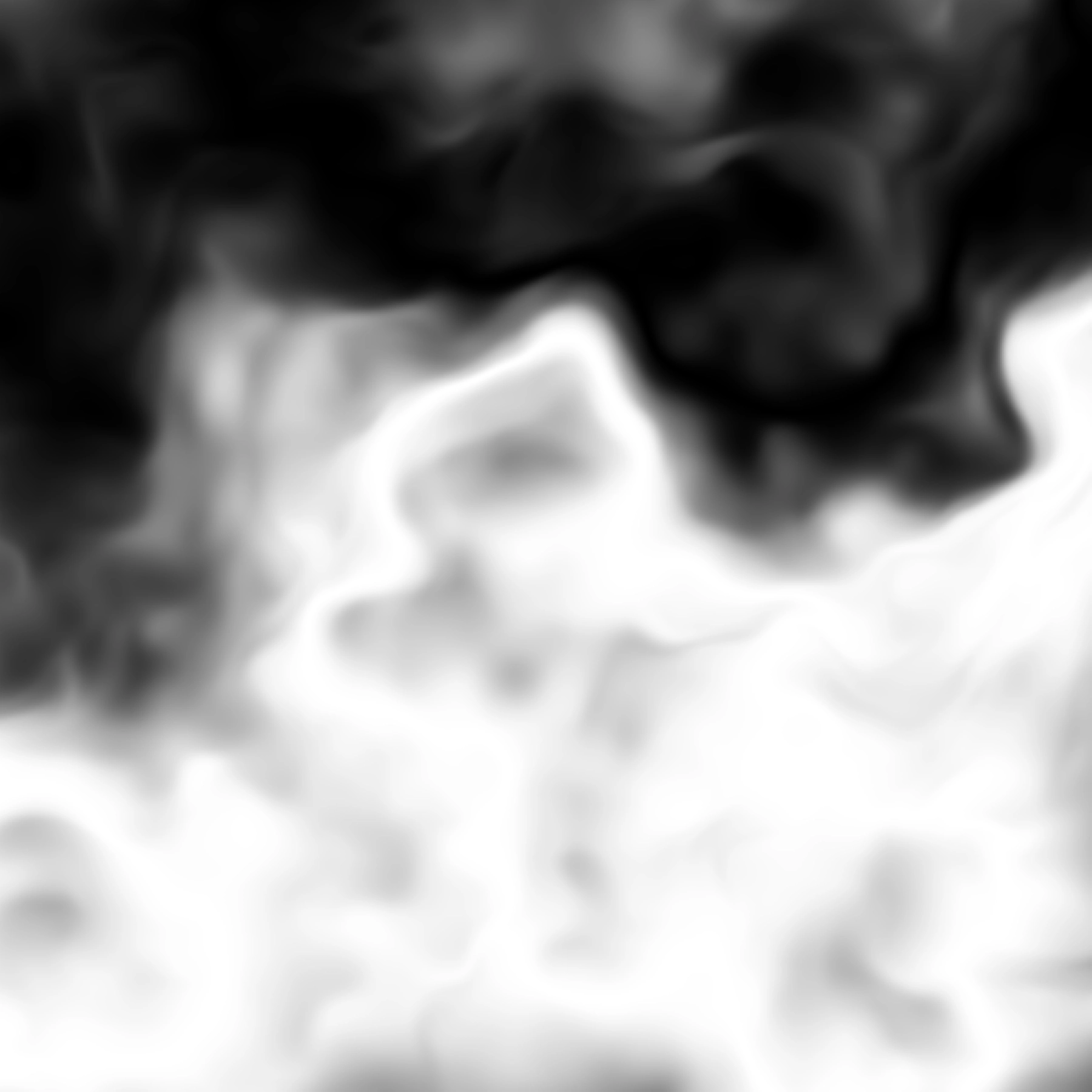
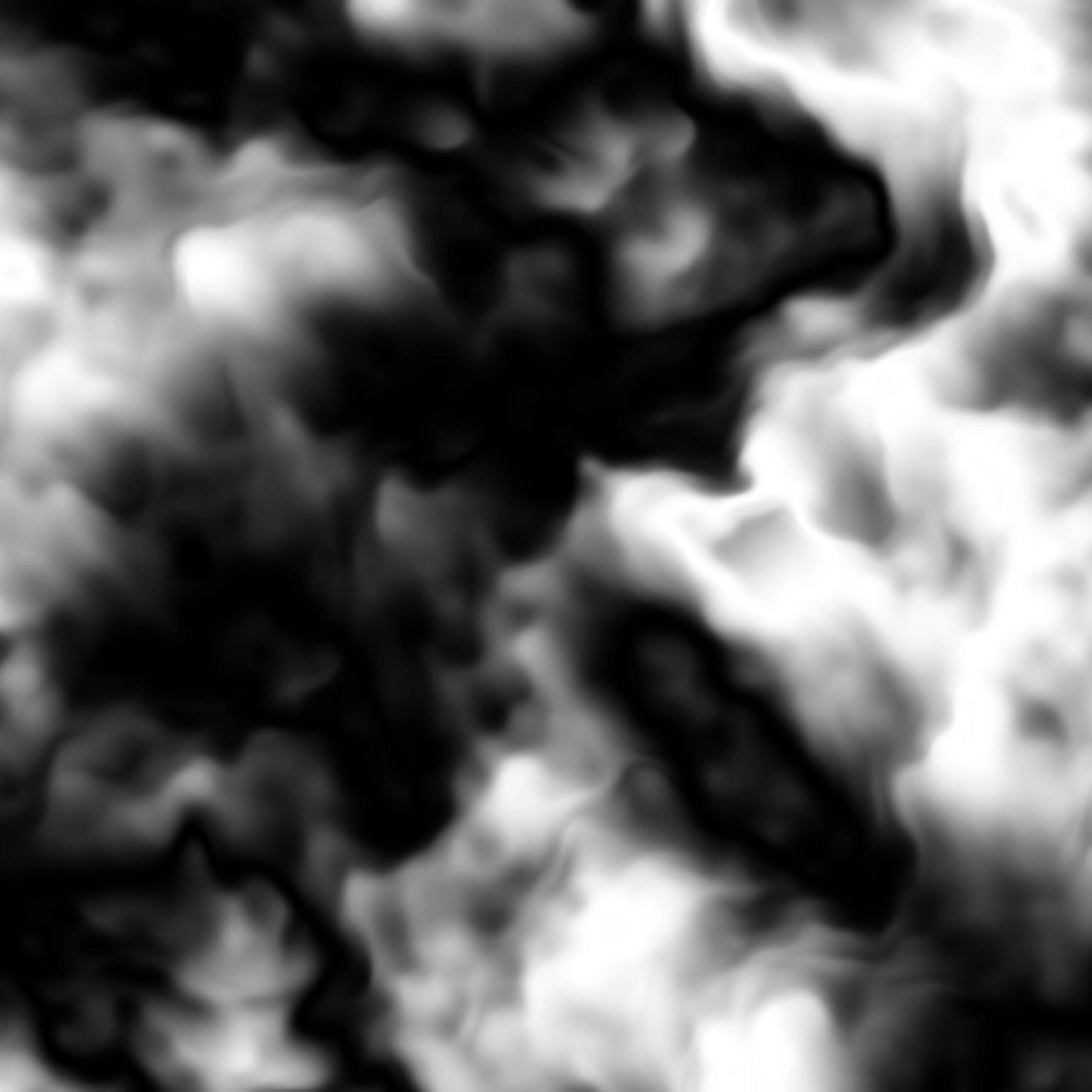
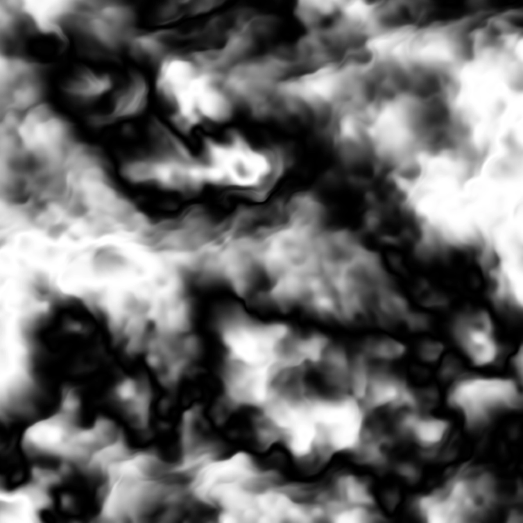
I started looking the Inigo Quilez’s domain warping technique for using it in p5.js, aiming to explore distortions in coordinate spaces and generate rich, organic textures. The images below illustrate the process, beginning with a fBm noise function and progressively increasing complexity by recursively warping the input domain.
Inigo Quilez’s article focuses on shaders, which are essentially functions that modify a pixel based on its position on the screen. Since I wanted to integrate this technique into p5.js, I had to adapt the logic to work with a pixel grid. Without a formal background in mathematics or computer science, my approach relies on understanding the logic and adapting it to my own skills and habits in p5.js.
Instead of modifying individual pixels directly through a shader, I use a Perlin noise function to distort the x and y coordinates of each grid cell.
This is a simplified interpretation of Inigo Quilez’s technique, not the exact method he uses. In this setup, if f(p) represents the color of a given cell, I can implement this in p5.js using noise(x, y) for each cell in the grid.
  createCanvas(400, 400);
  background(220);
  const nb = 150;
  const space = width/nb;
  const vn = random([0.1,0.05,0.01,0.005,0.001]);

  for(let i=0;i<width;i++){
    for(let j=0;j<height;j++){
      const n = noise(i*vn,j*vn)
      fill(n*255);
      stroke(n*255)
      rect(i,j,1)
    }
  }

noise(i*0.001,j*0.001)
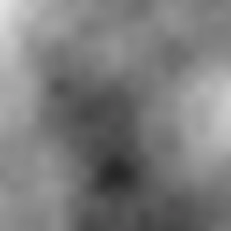
noise(i*0.005,j*0.005)
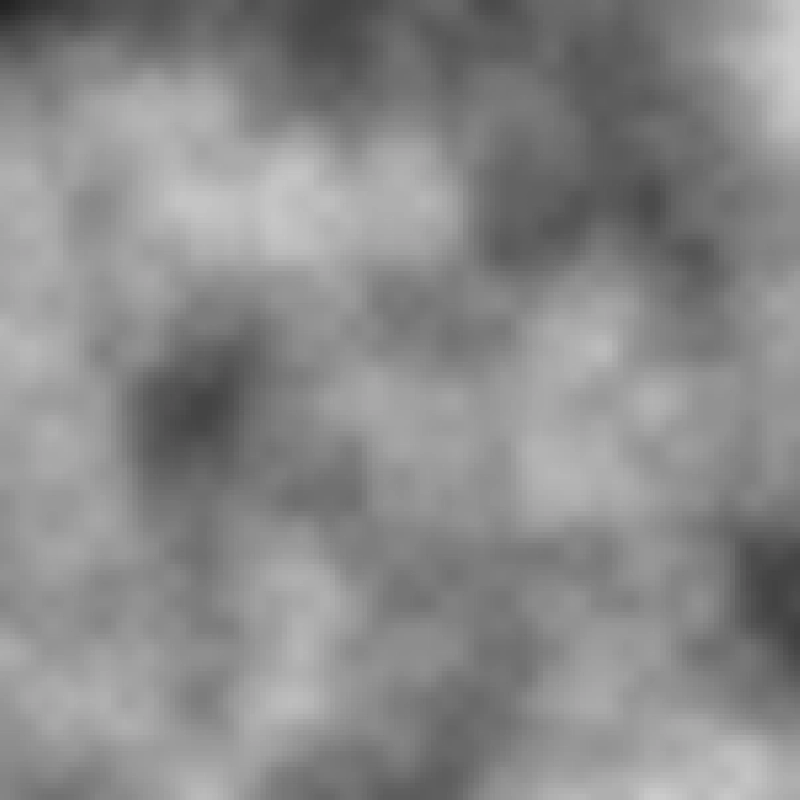
noise(i*0.01,j*0.01)
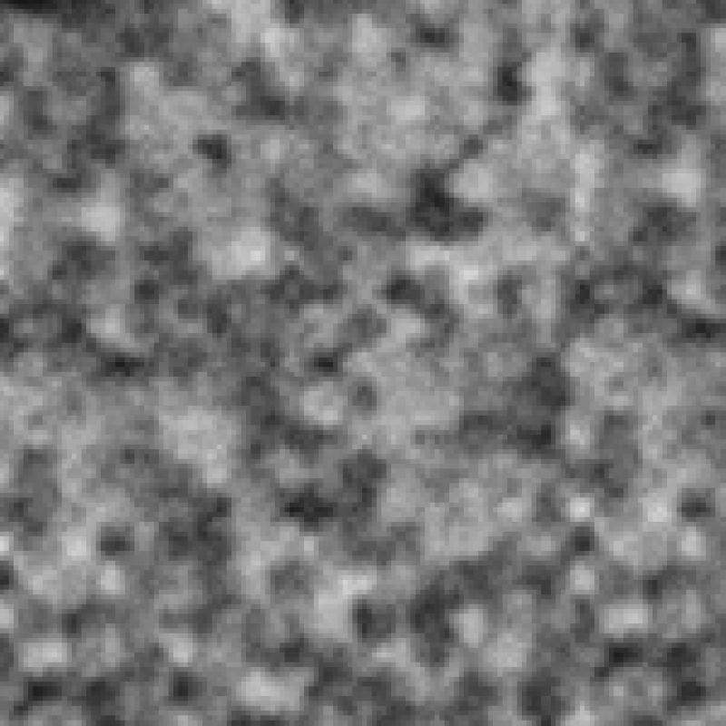
noise(i*0.05,j*0.05)
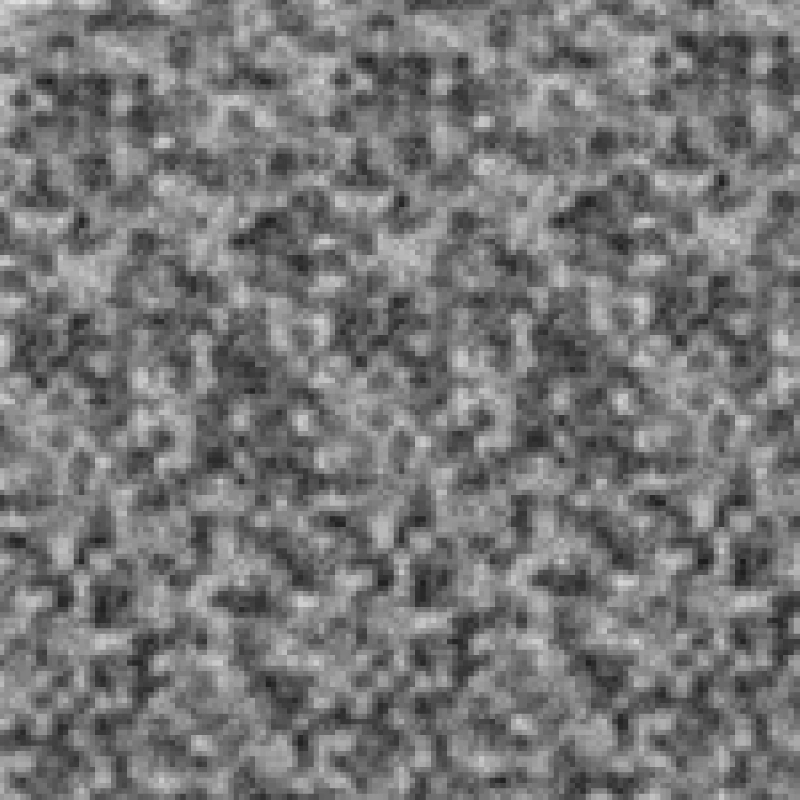
noise(i*0.1,j*0.1)
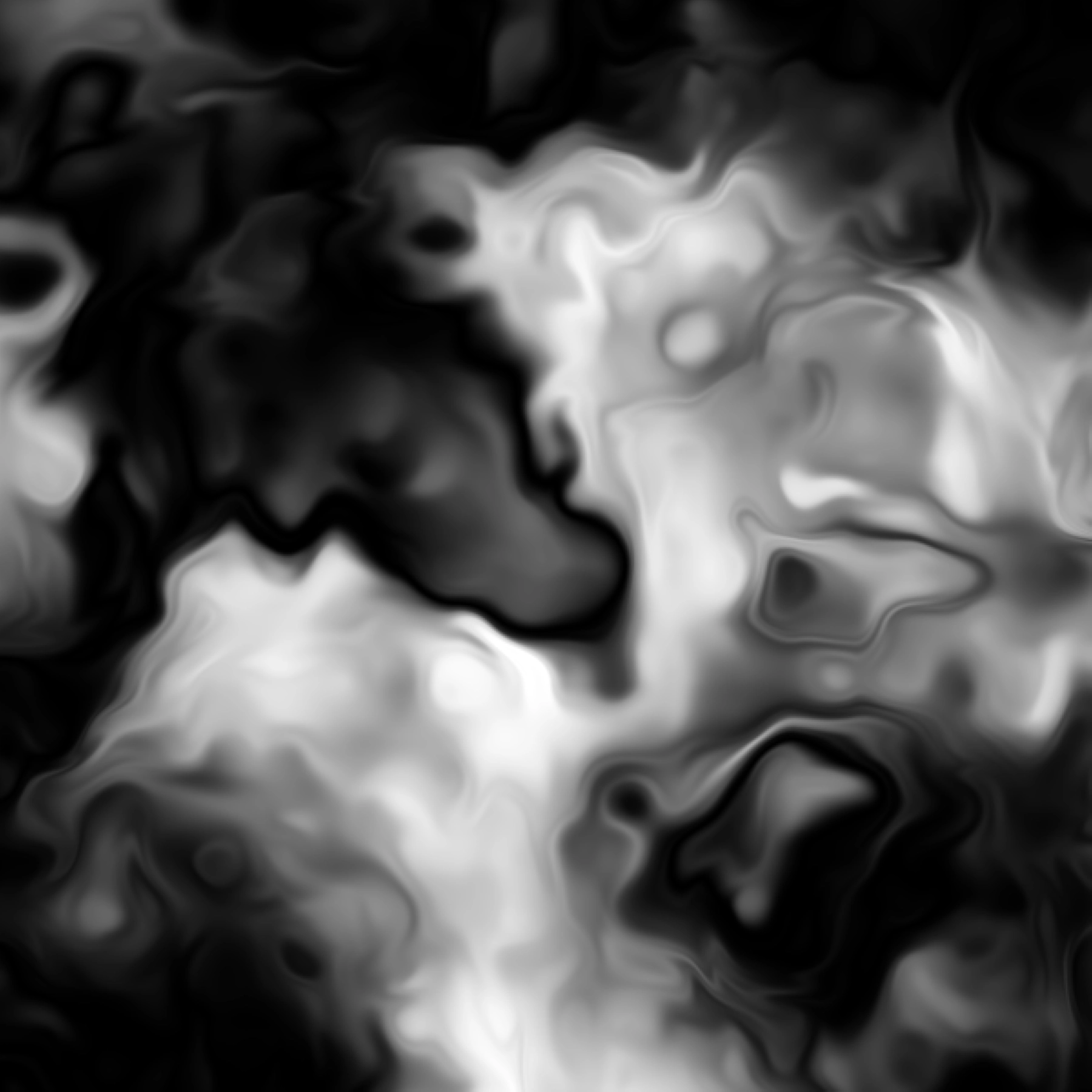
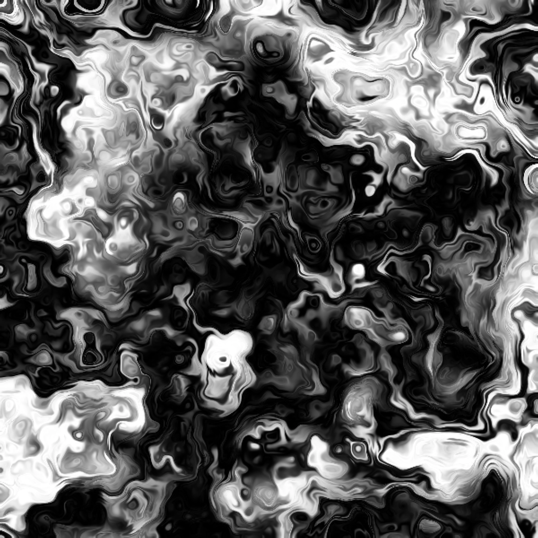
If I understand* Inigo's function correctly, I now need to apply a noise function within the parameters of another noise function. However, I must be careful with the values generated by noise. In p5.js, Perlin noise is normalized, meaning that `noise()` returns values between 0 and 1. But for this transformation, we need much smaller values to apply as offsets to the primary noise function on the x and y coordinates. Typically, on a 400x400px canvas, a value of **0.008** produces good results. So, we need to map the secondary noise function to output values close to **0.008** before applying it to the main noise calculation.
* Well… we’ll soon realize that this wasn’t exactly correct! 😆
createCanvas(400, 400);
background(220);
let nb = 150;
let space = width/nb;
vn2 = random([0.1,0.05,0.01,0.005,0.001]);

for(let i=0;i<width;i+=space){
  for(let j=0;j<height;j+=space){
    let vn = map(noise(i*vn2,j*vn2),0,1,0.001,0.05)
    let n = noise(i*vn,j*vn)
    stroke(n*255)
    rect(i,j,space)
  }
}
vn2 = 0.001
vn2 = 0.005
vn2 = 0.01
vn2 = 0.05
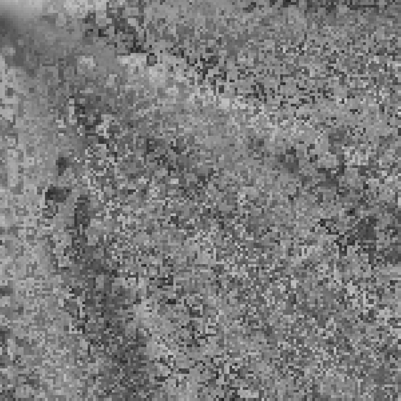
vn2 = 0.1
vn2 = 0.001
vn2 = 0.005
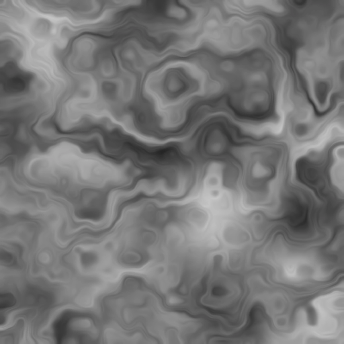
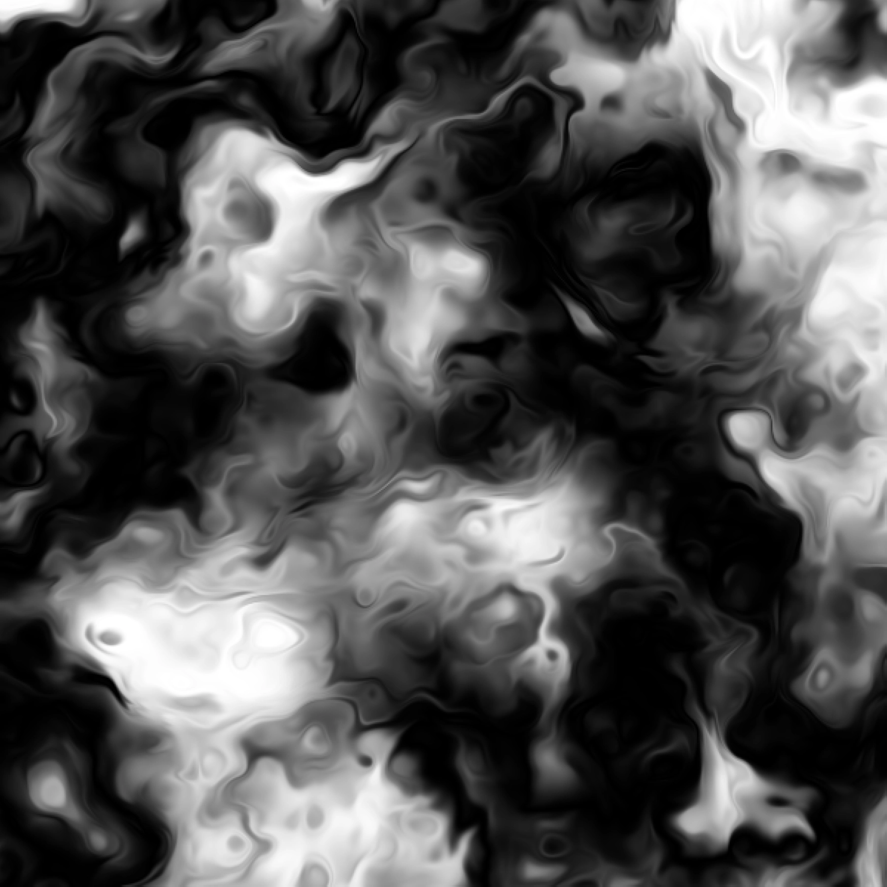
As seen in the two images, the noise produces an effect that appears to be distance-dependent relative to the (0,0) coordinates of the grid. At first, I suspected a proportionality issue, so I tested adding offsets to the noise calculations, but the problem persisted. Then, I considered introducing a second reference point within the noise function to add an extra dimension. This way, the x and y coordinates of each cell's position would have less influence on the overall distortion.
Before moving forward with this approach, however, let's first address and resolve this issue.
Upon further inspection, I realized that the issue was actually caused by an error how I used the formula. Instead of applying the correct domain warping function:
f(p) = fbm( p + fbm( p ))
I had mistakenly used:
f(p) = fbm( fbm( p )) (forgot to add p 🤦♂️)
This mistake caused the input coordinates to be overly compressed by feeding the result of the noise function directly into itself, rather than warping the domain with an additional noise layer. As a result, the distortion leads to the undesired radial effect.
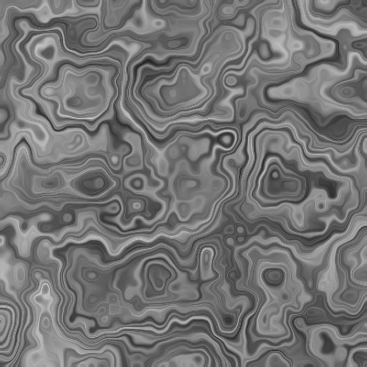
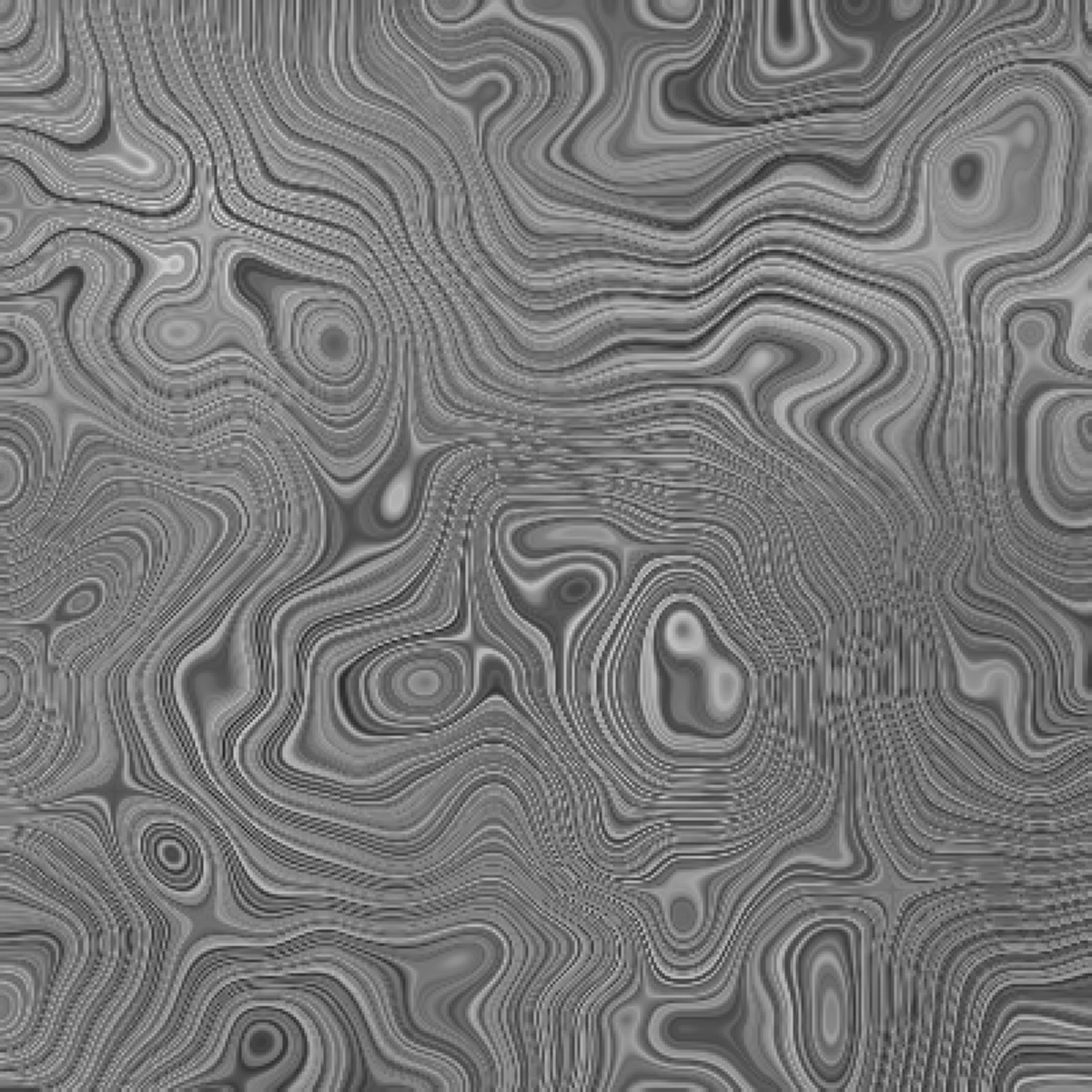
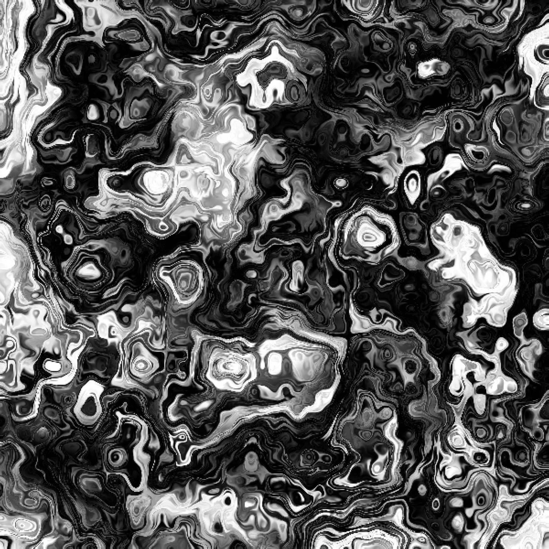
To better understand the behavior of domain warping in p5.js, I systematically tested different parameter values and their effects
on the generated patterns. The code snippet below demonstrates
the structure of the function used, with parameters a, b, and c controlling different aspects of the distortion:
a: Controls the base frequency of the
noise.
b: Defines the intensity of the domain
warping applied.
c: Influences the final noise
perturbation, adding finer details.
Note : a and b could be replaced by a single variable.
  function setup() {
    createCanvas(400, 400);
    background(220);
    const a = random(0.1);
    const b = random(0.1);
    const c = random([random(),random(150)]);
    console.log(a,b,c)
    for(let i=0;i<width;i++){
      for(let j=0;j<height;j++){
        const n1 = noise(i*a,j*a);
        const n = noise(i*b + n1,j*b + n1, n1*c);
        stroke(n*255)
        rect(i,j,1)
      }
    }
  }
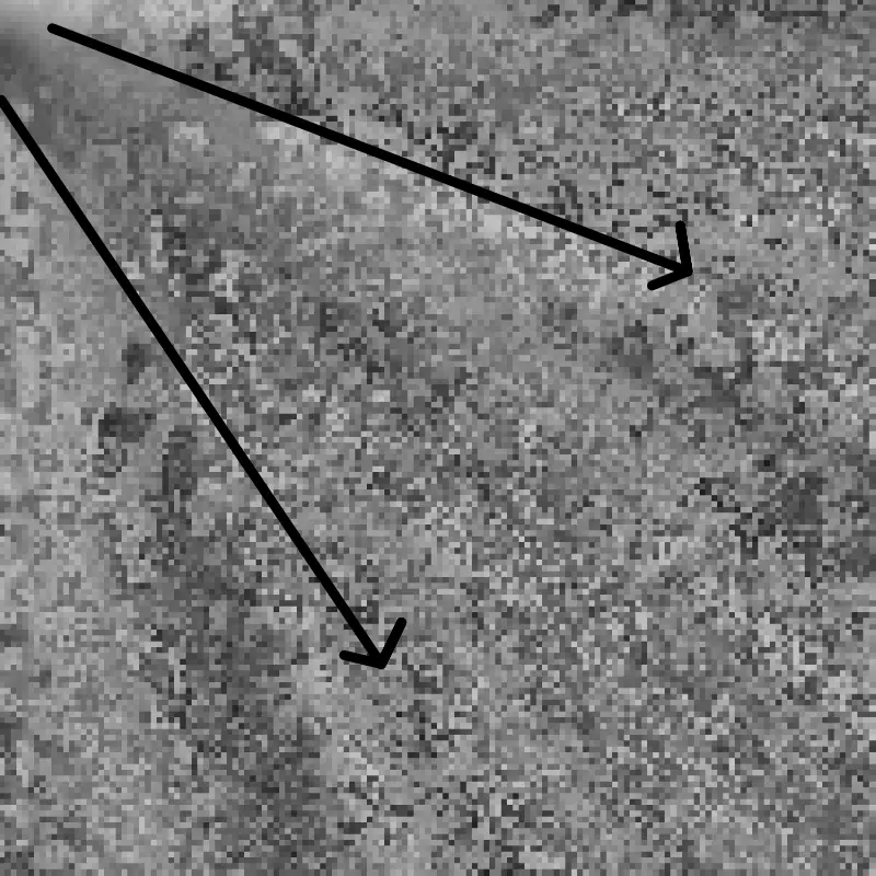
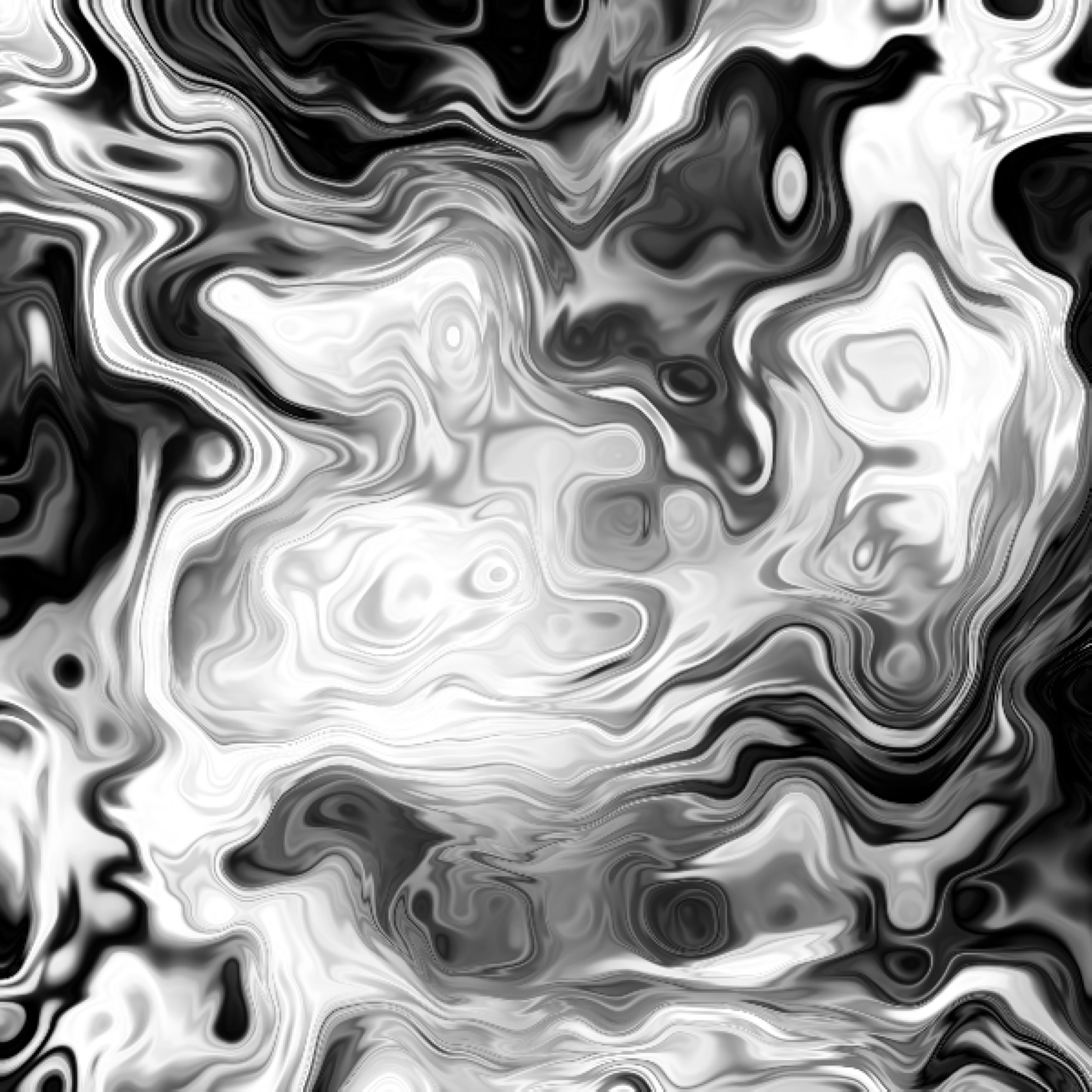
By adjusting these parameters, we achieved a controlled domain warping effect, significantly reducing the undesired distance bias.
a:0.008, b:0.008, c:0.01
a: 0.01, b: 0.01, c: 10
a: 0.01, b: 0.01, c: 50
a: 0.05, b: 0.05, c: 10
a: 0.05, b: 0.01, c: 10
a: 0.1, b: 0.005, c: 50
a: 0.001, b: 0.001, c: 100

a: 0.002, b: 0.003, c: 50
a: 0.004, b: 0.006, c: 50
a: 0.004, b: 0.006, c: 500
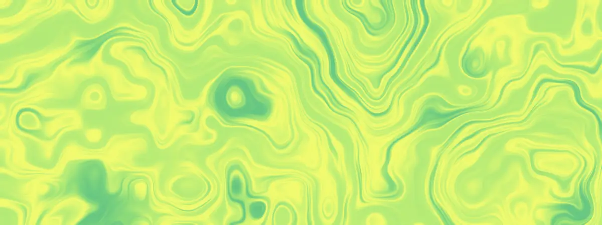
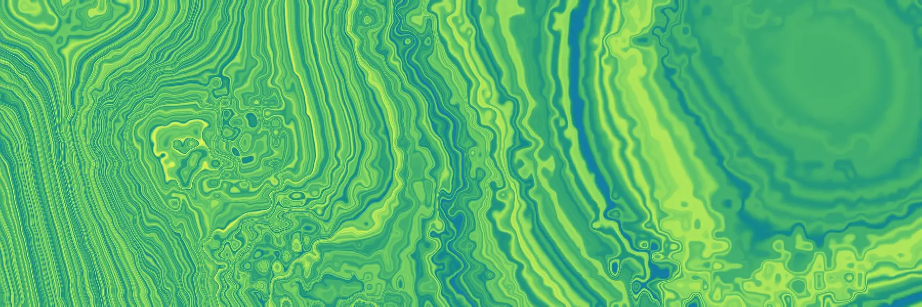
With spectral.js mix colors
Domain warping 1
However, stopping at
f(p) = fbm( p + fbm( p ))is not the only possibility. With the same recursive approach, one can extend this principle further to:
f(p) = fbm(p + fbm(p + fbm(p)))The complete implementation of this function is available at the end of the article.
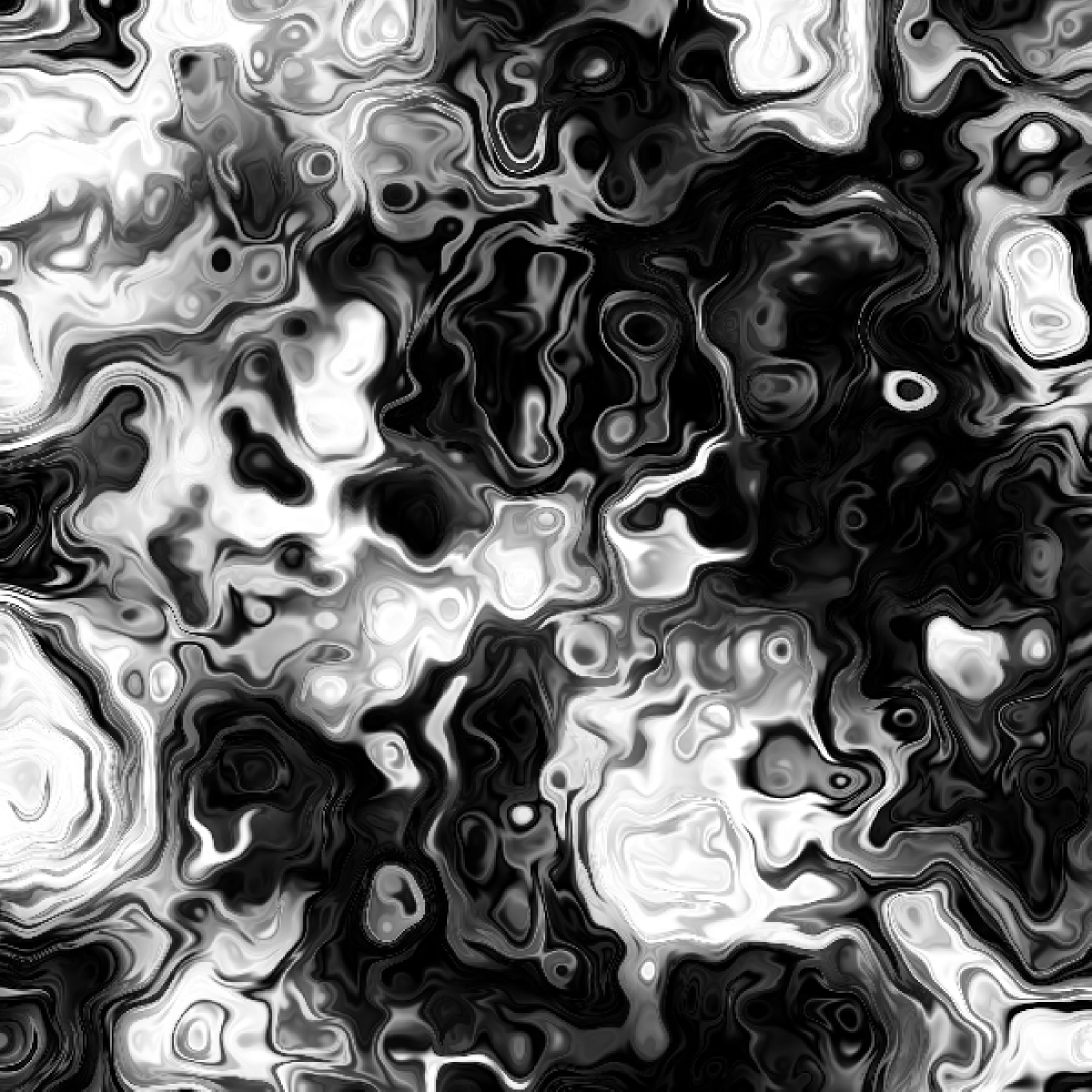
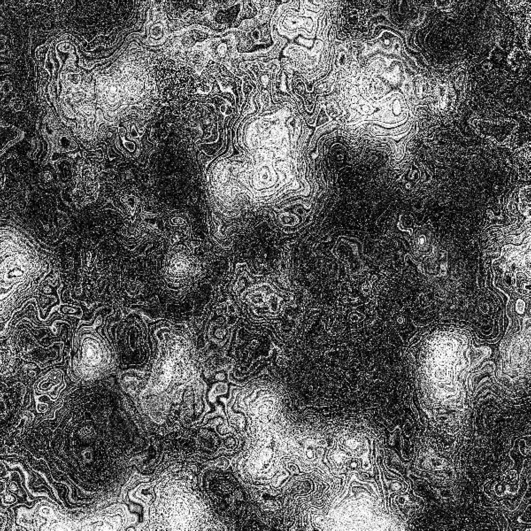
Before realizing my mistake in the formula, I continued experimenting
with different ways to mitigate the distance-based distortion. My
approach was to introduce a reference distance point, d, which measures the distance from each grid cell (i, j) to
a target point (target.x, target.y). This allowed for dynamic scaling of the noise effect based on position, rather than applying a uniform warping
across the entire grid.
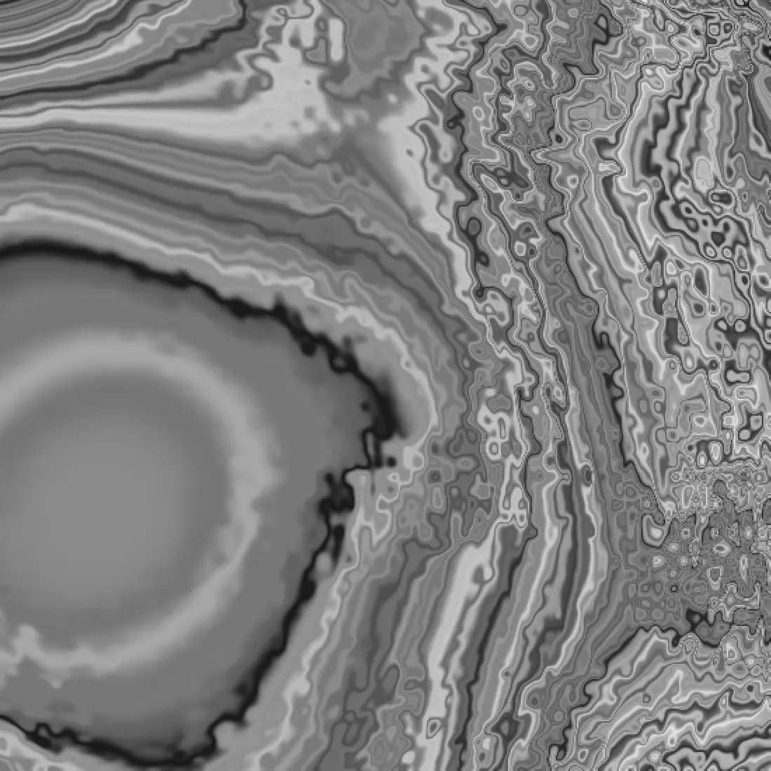
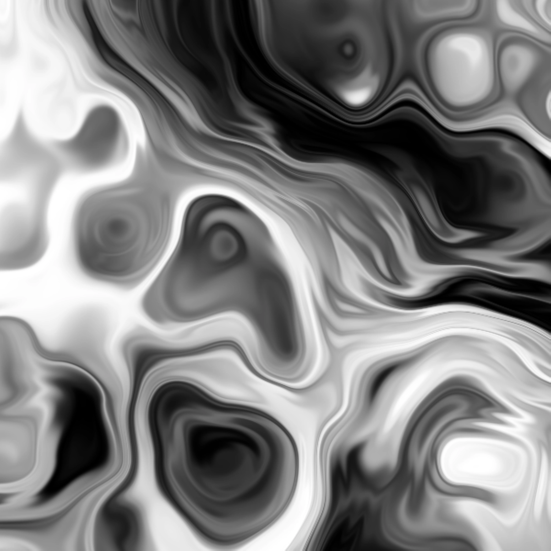
As I tend to experiment by intuition rather than reason, I ended up mixing three different noise functions into a massive "what the fuck" experiment. Instead of methodically debugging, I threw everything into the mix—creating something chaotic, unexpected, and strangely compelling.
This is a perfect example of serendipity in creative coding—where an unintended mistake becomes the seed of an entirely new artistic direction. The initial radial distortion, instead of being just a problem to solve, transformed into a feature that gave the piece its unique identity.
Later, when multiple targets are introduced, something chaotic, unexpected, and strangely compelling emerges, pushing the generative structure beyond simple radial patterns into a more complex and organic aesthetic.
  function setup(){
    createCanvas(400, 400);
    background(0);
    const diag = sqrt(width * width + height * height);
    const pw = random(0.1, 0.7);
    noStroke();
    const target = createVector(random(width), random(height)); // Single reference point
    noiseDetail(2, 0.9);

    for (let i = 0; i < width; i++) {
      for (let j = 0; j & height; j++) {

        const d = dist(i, j, target.x, target.y);
        const dn = d / diag * 0.5;
        const vn = map(noise(d * 0.01, i * 0.05, j * 0.05), 0, 1, 0.003, 0.004);
        const n2 = noise(i * vn + 3e9, j * vn) * dn;
        const n = noise(d * n2 * pow(dn, pw), 10000 + d * n2 * pow(dn, pw));
        stroke(n*255);
        rect(i, j, 1);
      }
    }
  }
In this approach, each pixel's noise is influenced by a single reference
point, target. The steps are:
d from the pixel to
the reference point.
dn to control the intensity
of the transformation.
vn by mapping Perlin noise values
to a small range. This controls the scale of the noise-based displacement,
introducing fine-grained local variations.
n2,
which combines vn and dn to affect the strength
of the displacement.
n2 into the final noise function to
produce the final warped output.
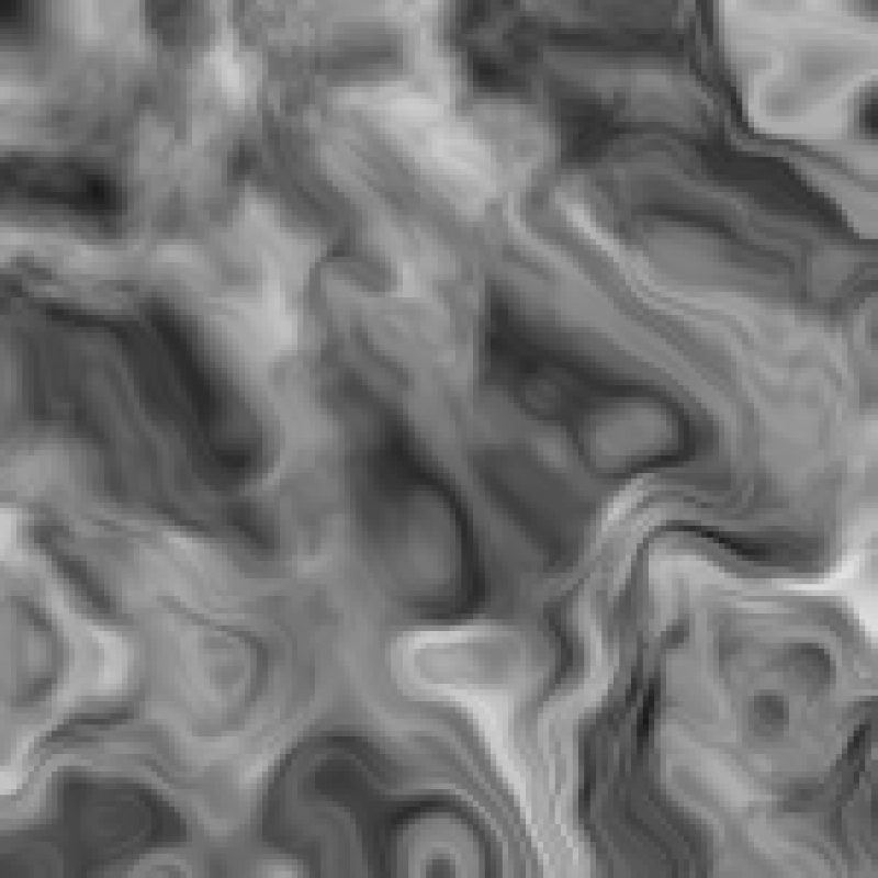
This method introduced a radial pattern that, while unintended, became an interesting structural element in the composition.
See the code in the p5 Editor
Domain warping 1
Domain warping 2
Domain warping 3
With spectral.js mix colors
Domain warping 1
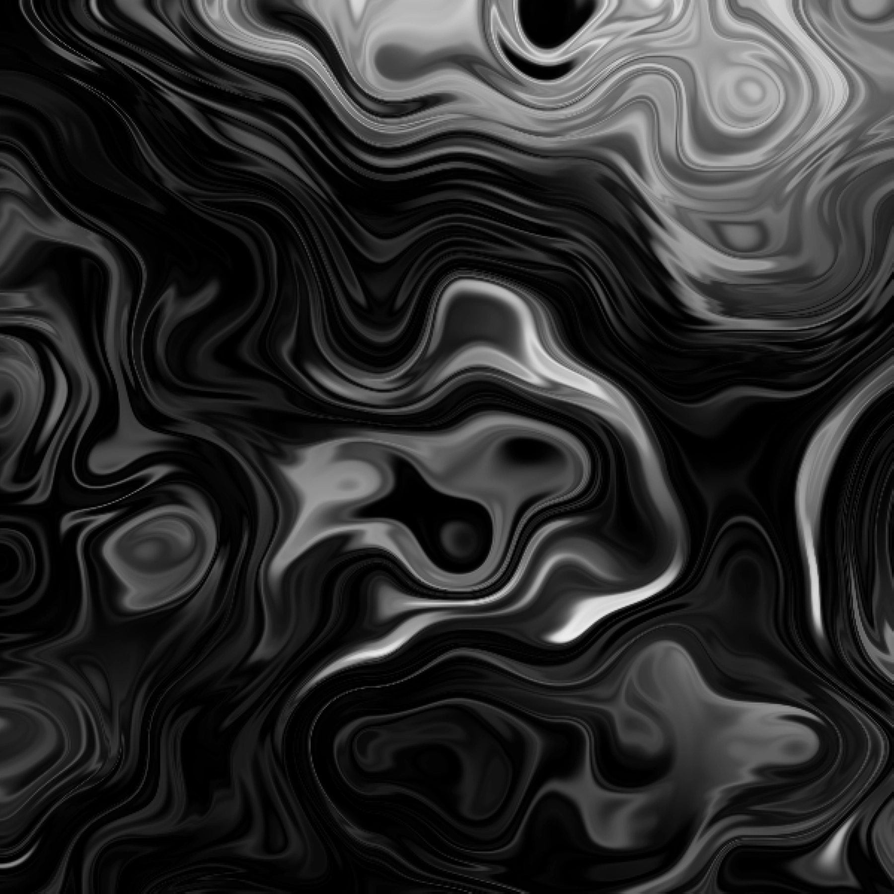
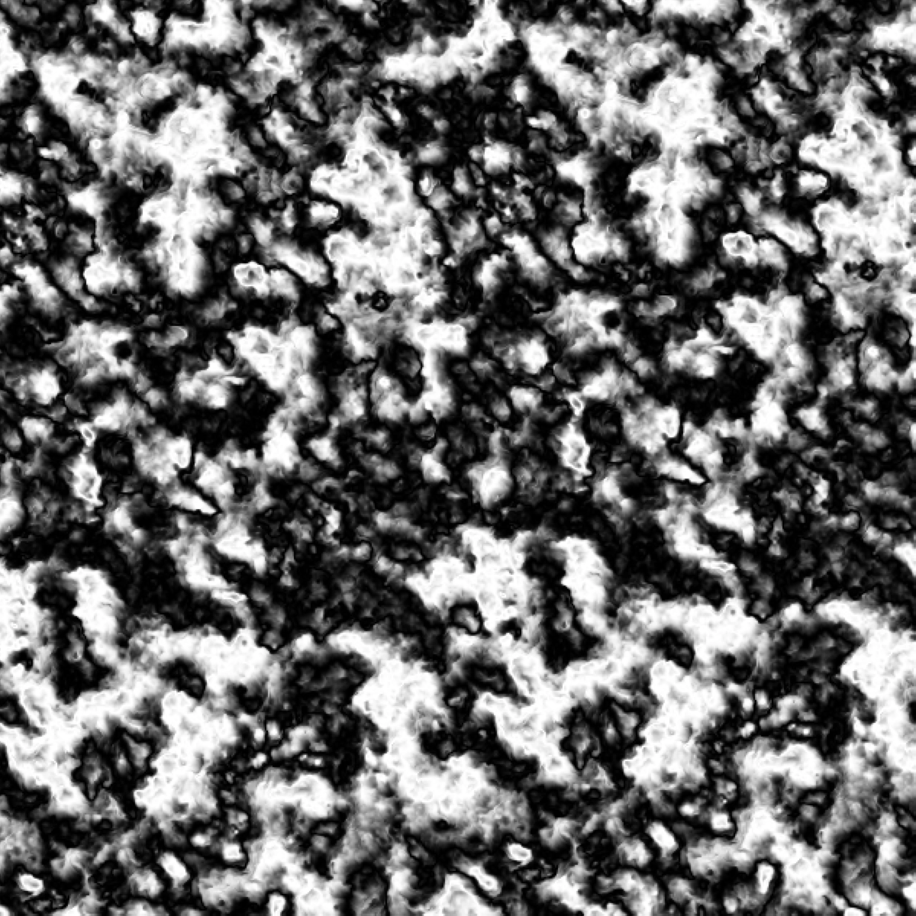
At this stage, I was still unaware of my mistake in the formula. However, I wanted to refine the effect by making the warping less dependent on a single reference point. This led me to experiment with multiple reference points—a crucial step in evolving the aesthetic further.
This transition from a single reference to multiple reference points further reduced the radial effect, adding more complexity and depth to the distortion.
In the previous step, the domain warping was influenced by a single reference point, leading to a radial distortion where the noise effect
intensified with distance. To mitigate this issue, I modified the approach
by introducing multiple reference points (targets), distributing the influence across different areas of the canvas.
  const numTargets = 3;
  const targets = [];
  const vn =  0.009;
  const diag = sqrt(width*width + height*height)
  ...
  for (let i = 0; i < numTargets; i++) {
    targets.push(createVector(random(width), random(height)));
    }

  for (let target of targets) {
    const di = dist(i, y, target.x, target.y);
    const dn = di / diag * 0.75;
  }
Instead of using a single target, this loop iterates over multiple target points.
di represents the distance from the current pixel (i, y) to each target point.
dn normalizes di relative to the canvas diagonal,
ensuring that the influence scales smoothly.
  const n2 = noise(i * vn, y * vn) * pow(dn, pw2);
  const n = noise(di * n2 * pow(dn, pw), 123 + di * n2 * pow(dn, pw), sin(dn * di * TAU * 0.25));
The noise function is now dependent on each target point’s distance, rather than a single fixed reference.
n2 applies a secondary Perlin noise, weighted by the distance
exponentiation pow(dn, pw2), to introduce localized
variations.
n further distorts the noise by combining:
dn * di to introduce
oscillatory variations.
totalInfluence += n;
The final noise value is accumulated over all target points, meaning that each pixel is influenced by multiple references.
  totalInfluence /= numTargets;
  fill(colFill);
  if (totalInfluence > 0.5) rect(i, y, 1, 1);
The accumulated noise influence is averaged over all numTargets. If totalInfluence exceeds 0.5, a pixel is
drawn.
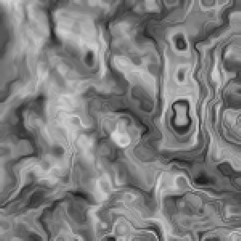
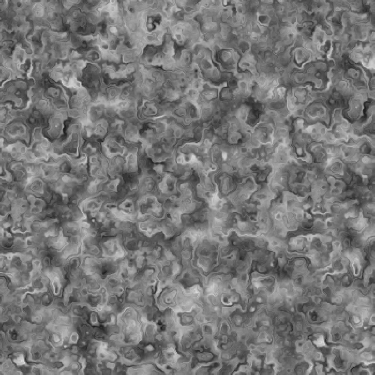
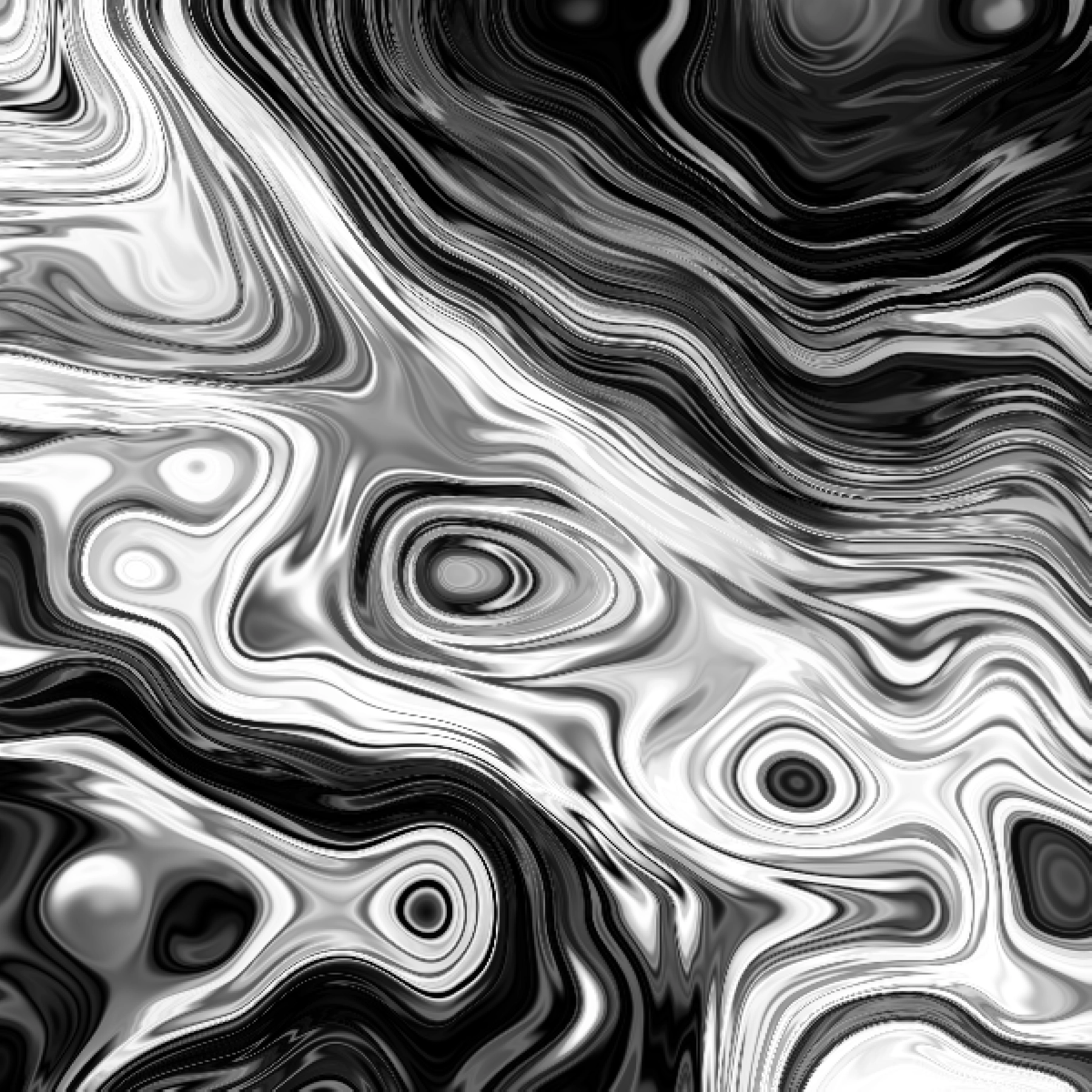
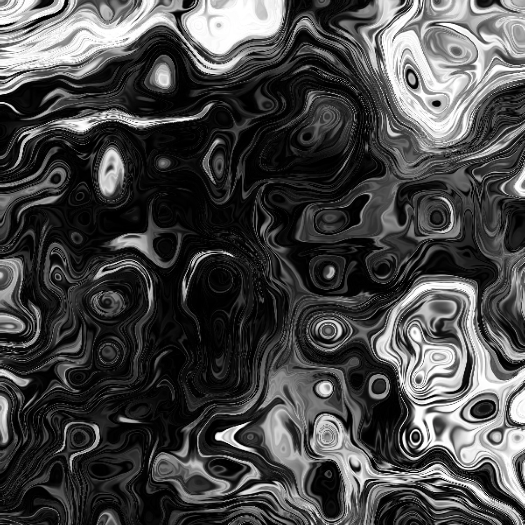
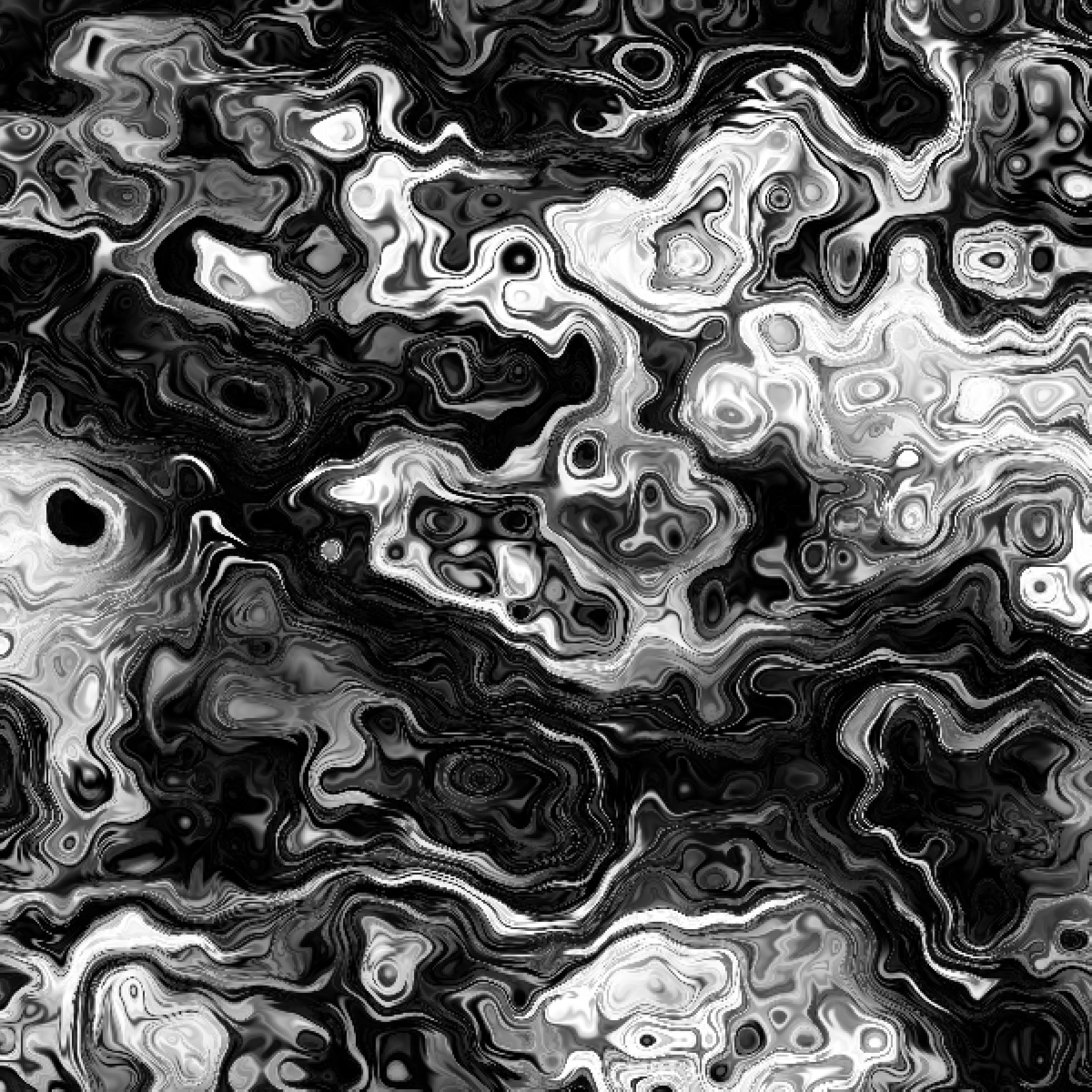
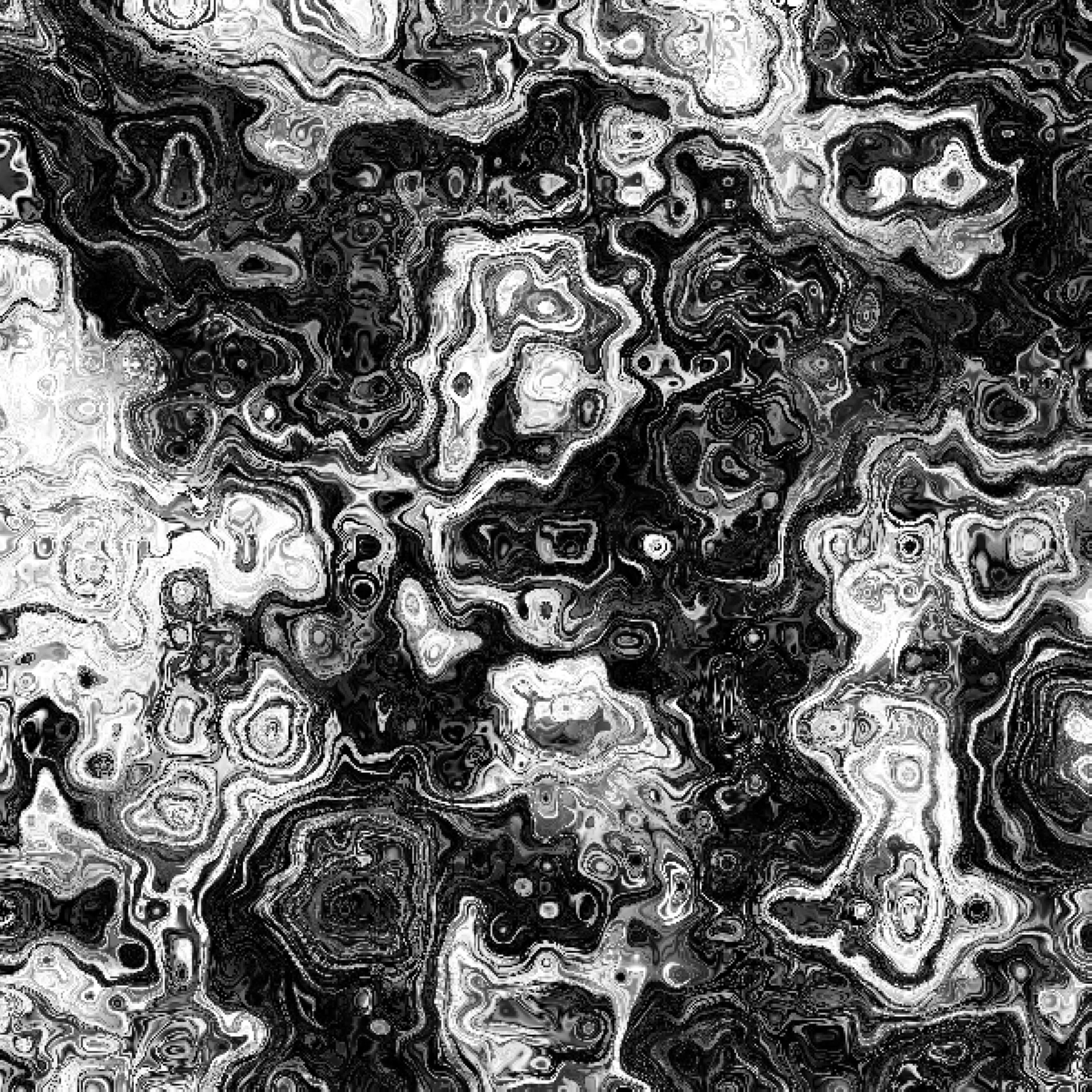
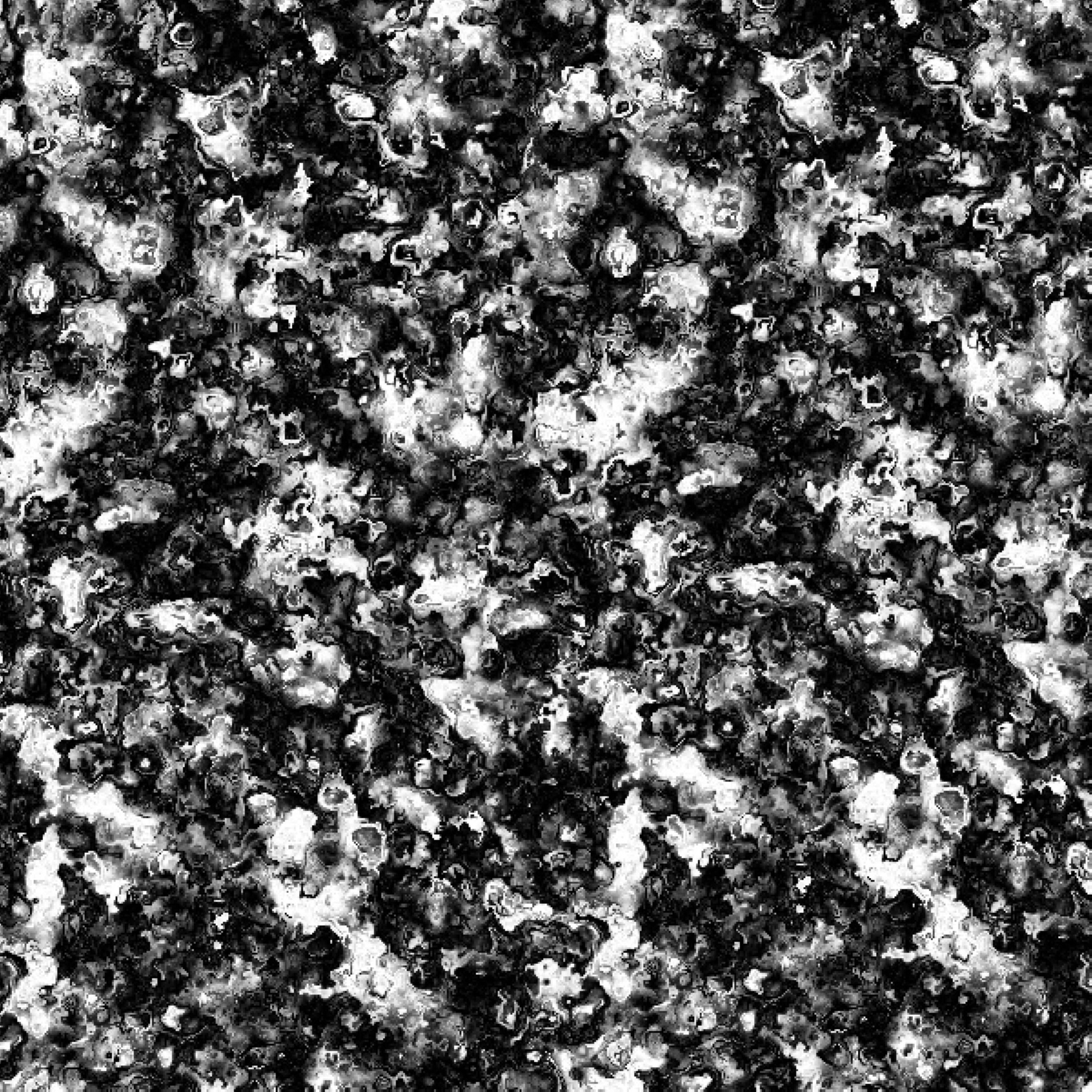
By introducing multiple reference points, the domain warping effect became more distributed and less dependent on a single central influence.
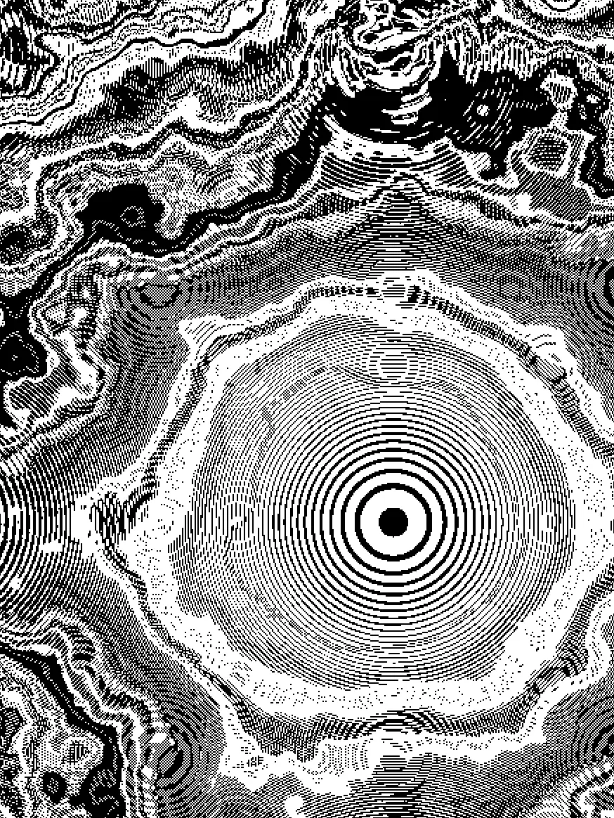
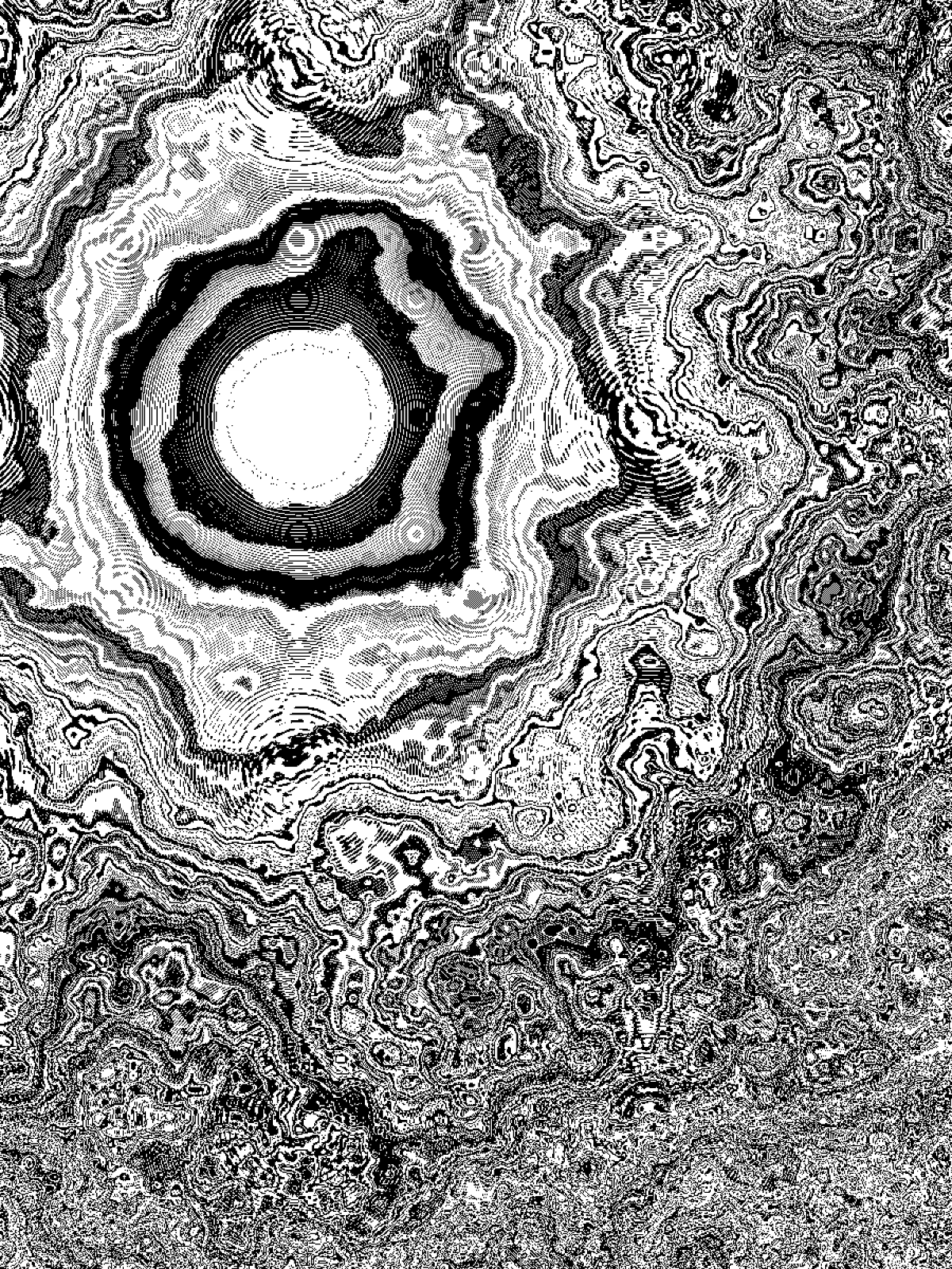
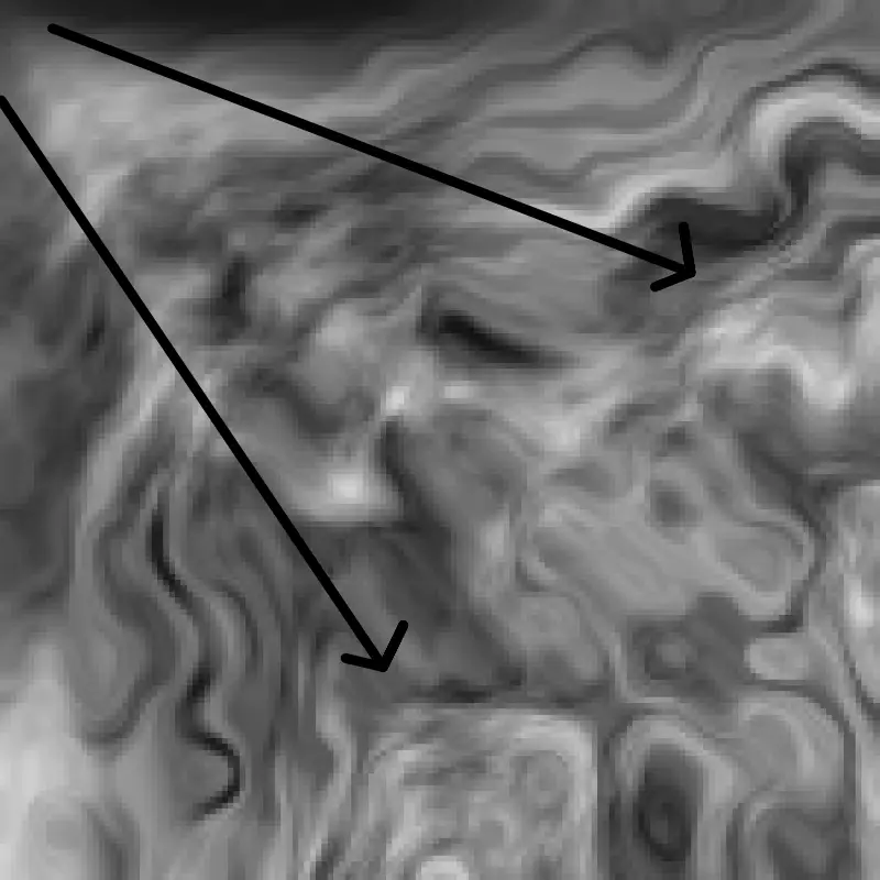
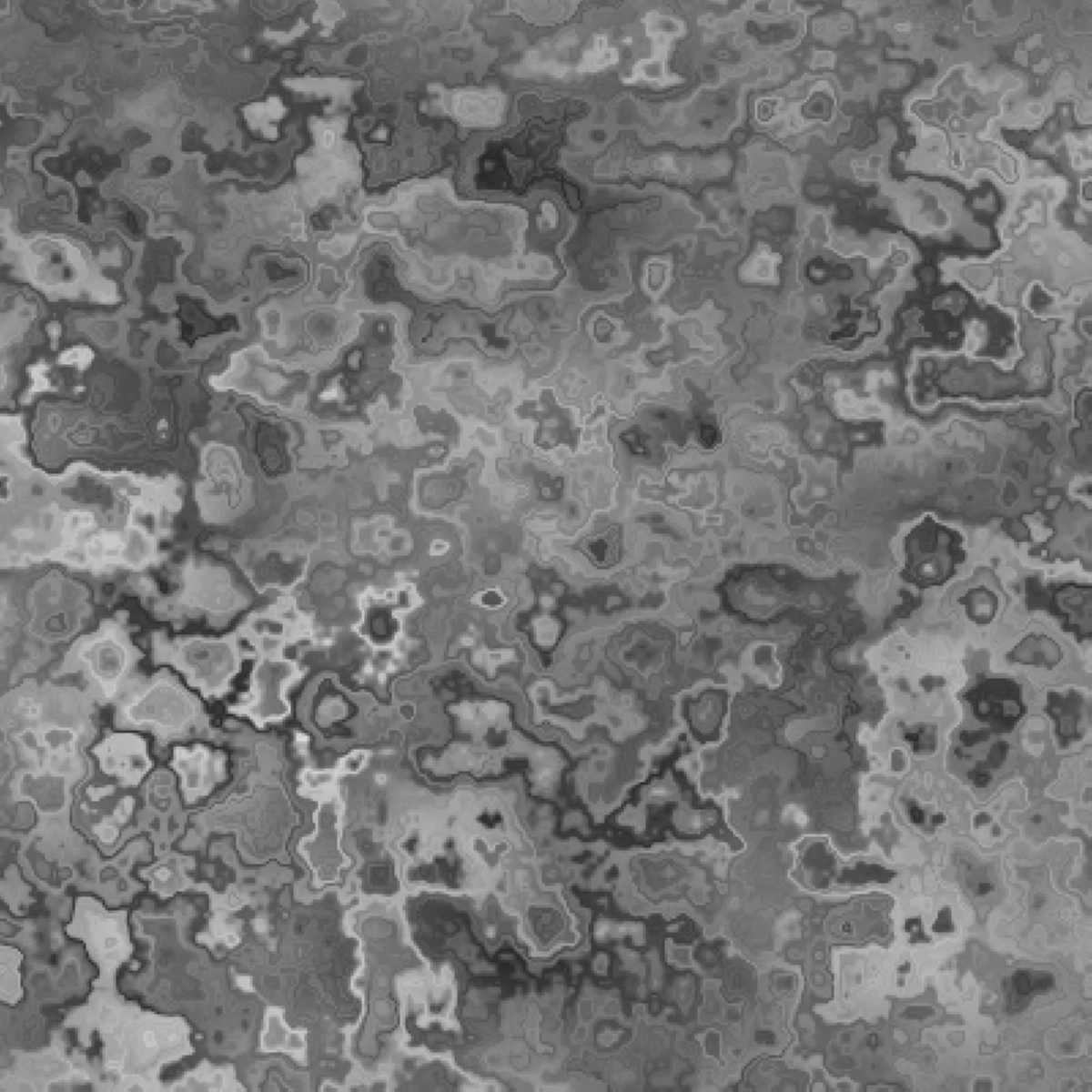
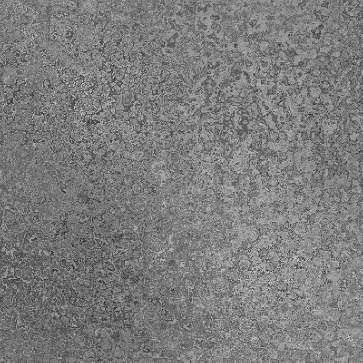
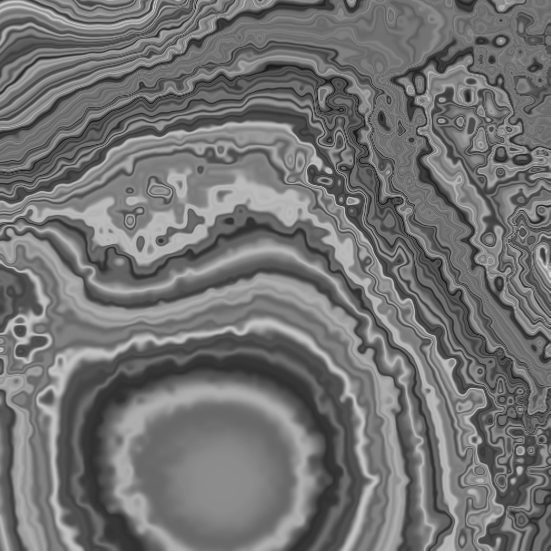
The results exhibit several notable characteristics:
In some areas, especially where reference points have overlapping influences, concentric circular structures emerge. This is particularly visible where interference patterns create nested rings, similar to geological formations or ripple effects. This occurs because the warping effect is applied relative to multiple distance fields, leading to overlapping distortions.
Some regions maintain a structured, layered flow, while others appear more chaotic and turbulent. The interaction of Perlin noise scaling with distance-based modulation creates sections where lines remain smooth and organized, while others break down into high-frequency patterns. Certain areas showcase dense, chaotic textures, while others exhibit clearly defined concentric distortions.
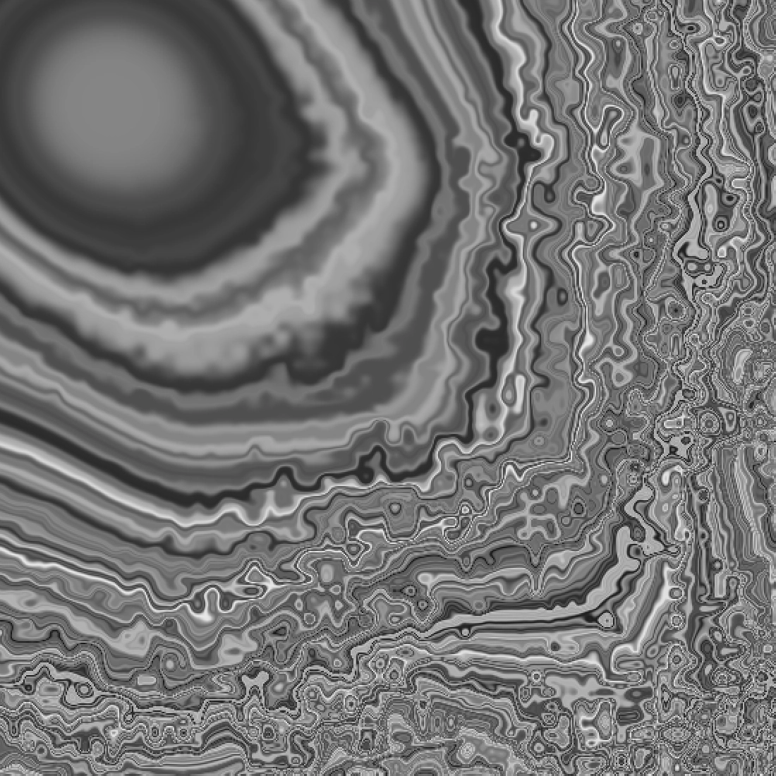
In certain areas, small-scale artifacts resembling halftone printing patterns appear. This likely results from the granularity of the grid combined with non-linear noise transformations, introducing pixel-level discontinuities. Some regions contain smoothly transitioning gradient bands, while others display sharp, high-frequency textural effects.
The introduction of multiple reference points successfully disrupted the initial radial symmetry, giving rise to new patterns of interference and structured layering. This shift transformed the composition from a predictable distortion into a more dynamic and evolving system.
Now, the balance between structured forms and chaotic variations is no longer dictated by a single point but emerges from the interplay of multiple influences. This distributed complexity opens up new possibilities for controlling the generative process, where subtle variations in reference point distribution can significantly alter the final aesthetic.
"var i(ant)" will be minted on fxHash with 300 unique editions. Visit the fxHash project page to mint and explore more.
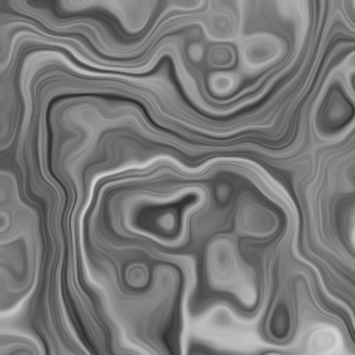
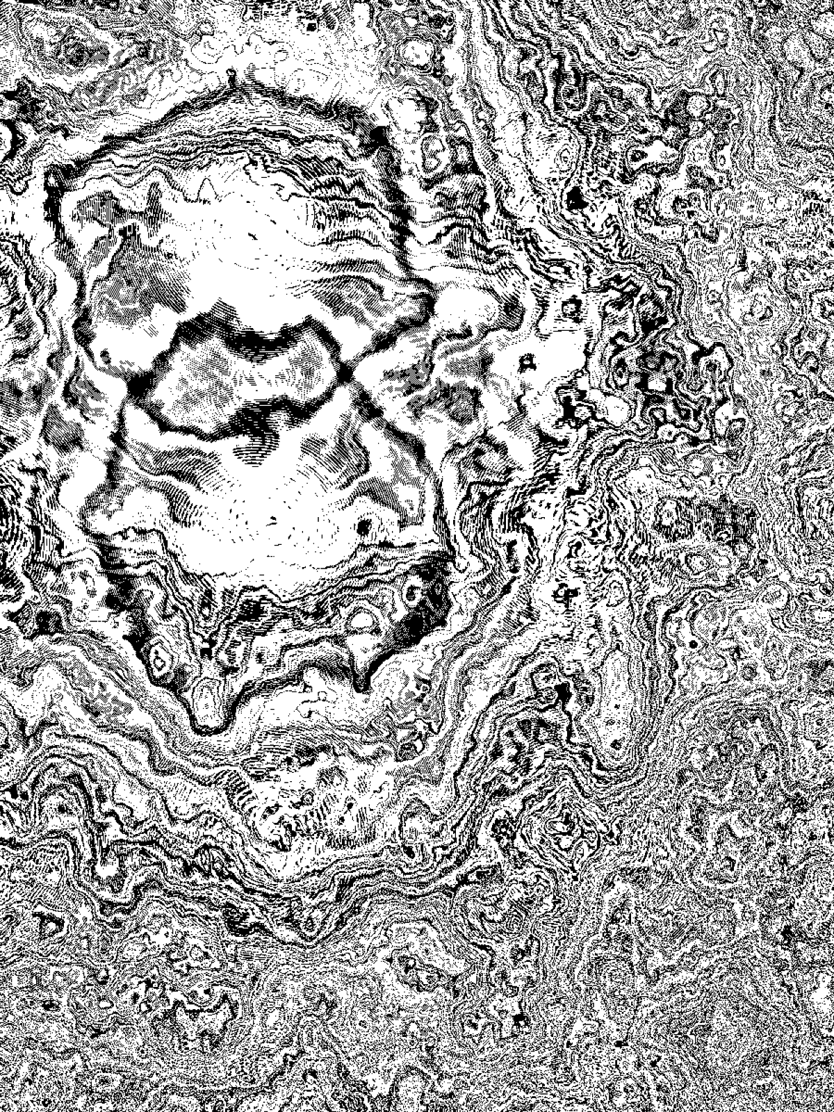
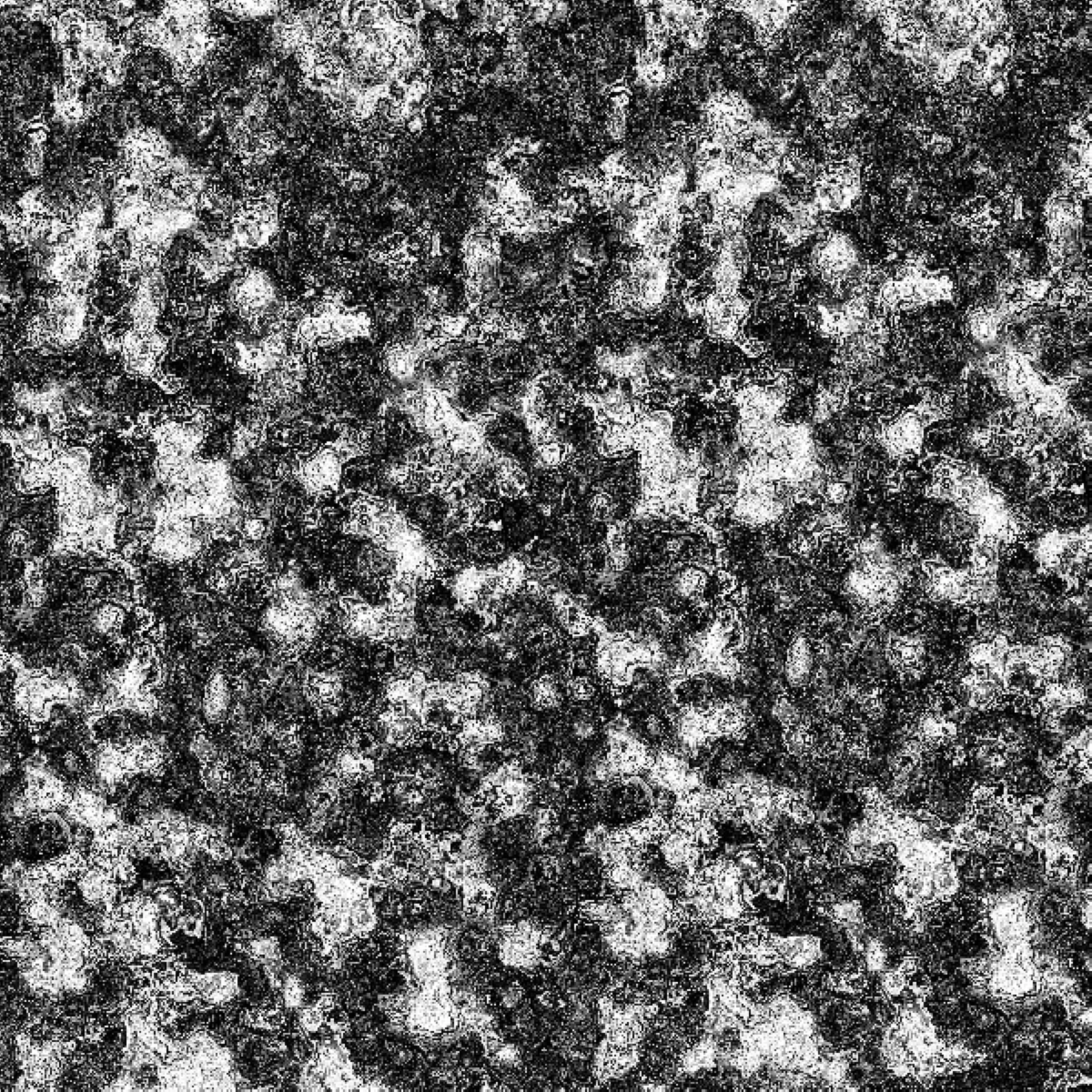
f(p) = fbm(p + fbm(p + fbm(p)))
In this section, we will explore the function:
f(p) = fbm(p + fbm(p + fbm(p)))
It is important to note that we are using the noise() function
from p5.js rather than the original Fractional Brownian Motion (fBm) implementation
by Inigo Quilez. The reason for this choice is twofold: it is more practical for
implementation within p5.js, and the results remain visually similar.
The following p5.js code implements this recursive fBm function, layering multiple noise evaluations to generate intricate textures.
function setup() {
  createCanvas(600, 600);
  background(220);
  const a = random(0.05);
  const b = random(150);
  console.log("a = " + a, "b = " + b);

  for (let i = 0; i < width; i++) {
    for (let j = 0; j < height; j++) {
      const n2 = noise(i * a, j * a);
      const n1 = noise(i * a + n2, j * a + n2, n2 * b);
      const n = noise(i * a + n1 + n2, j * a + n1 + n2, n1 * b);

      let col = lerpColor(color("#FFF"), color("#000"), (1 + sin((n + n2 + n1) * TAU)) / 2);
      stroke(col);
      fill(col);
      rect(i, j, 1);
    }
  }
}


n2 = noise(i * a, j * a).
n1 = noise(i * a + n2, j * a + n2, n2 * b).
n = noise(i * a + n1 + n2, j * a + n1 + n2, n1 * b).
lerpColor() and a sine transformation for smoother contrast.
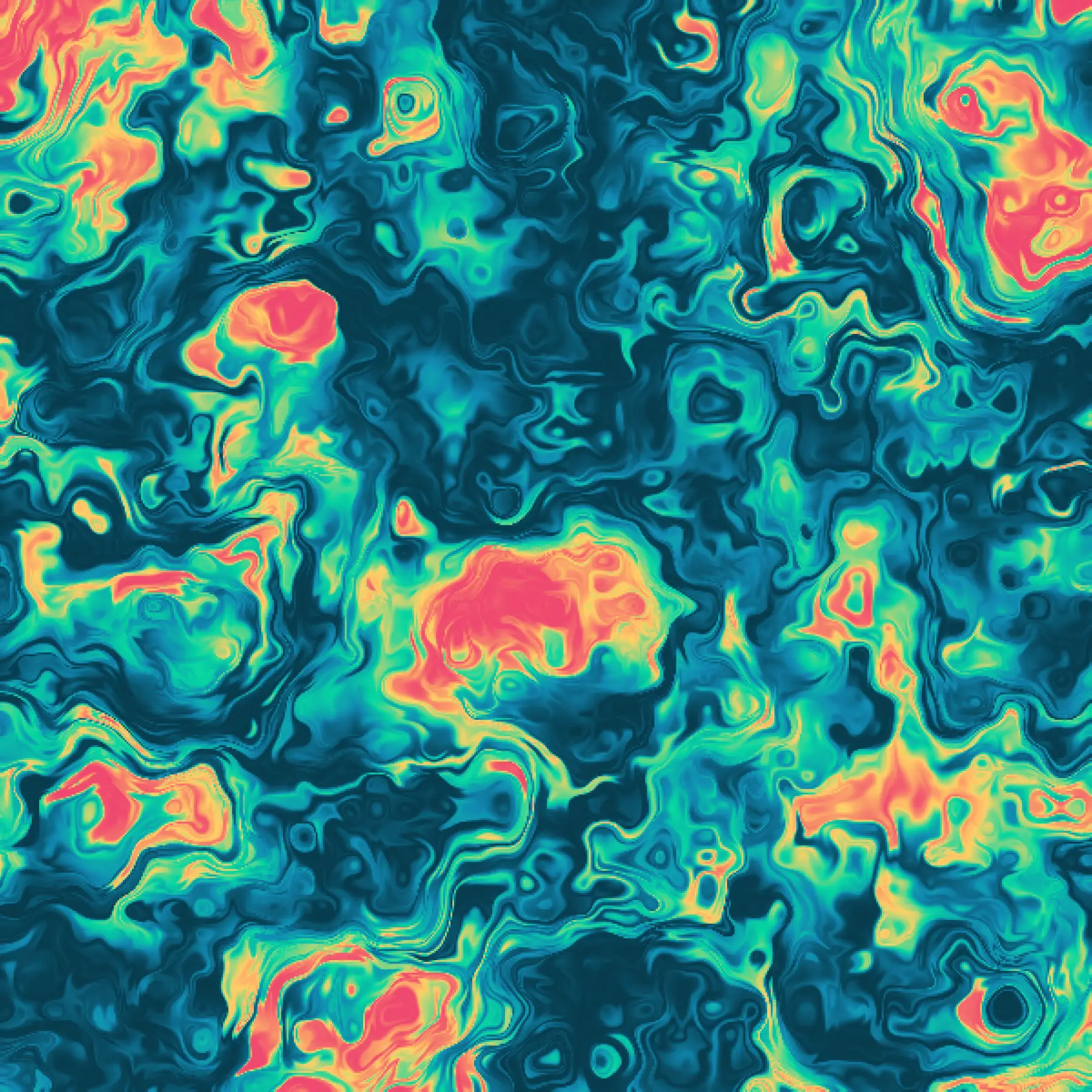
Domain warping 1
Thanks for sticking around till the end!
"var i(ant)" will be minted on fxHash with 300 unique editions. Visit the fxHash project page to mint and explore more.